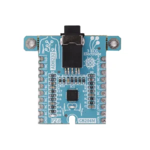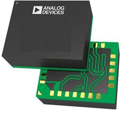
ADPD188GG, ortam ışığından ve senkronize yansıyan ışık yayan diyot (LED) darbelerinden gelen optik sinyalleri ölçmek için tasarlanmış eksiksiz bir fotometrik sistemdir. Senkron ölçüm, hem dc hem de ac ortam ışığı girişiminin sınıfının en iyisi olarak reddedilmesini sağlar. Modül, yüksek verimli bir fotometrik ön ucu, iki LED’i ve iki fotodiyodu (PD) birleştirir.
Uygulamaya özel entegre devrenin (ASIC) ön ucu, 14 bitlik bir analog-dijital dönüştürücü (ADC) olan bir kontrol bloğundan oluşur. Kontrol devresi esnek LED sinyali ve senkron algılamayı içerir.
Analog ön uç (AFE), genellikle ortam ışığının neden olduğu modüle edilmiş girişim nedeniyle sinyal kaymasını ve bozulmayı sınıfının en iyisi olarak reddeder.
Özellikler
- Output type: Digital – SPI and I2C
- ADC Resolution: 14 Bit
- Type of filter: IR cut filter
- Wavelength Peak: Green: 525nm PD1: 0.4nm PD2: 0.8nm
Uygulamalar
- Optik kalp atış hızı izleme
- Yansıtıcı SpO2 ölçümü
- CNIBP ölçümü
Gebra ADPD188GG Mödülü
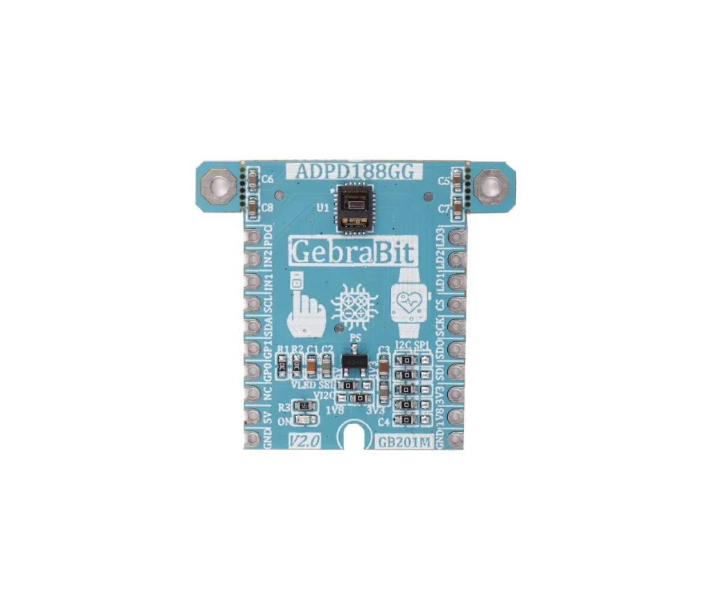
- Sensör pinlerine ulaşmanın zor olduğu göz önüne alındığında, sensörünün donanım ve yazılım geliştirmesi için kullanıcının bir starter devresine ve sürücüsüne ihtiyacı vardır. GebraMS kullanıcıların rahatlığı için Gebra ADPD188GG devresini hazırladı. Kullanıcılar bu sensörün en önemli pinlerine bu devre aracılığıyla kolaylıkla erişebilirler
- Gebra ADPD188GG BreadBoard’a yerleştirmeniz, ardından Arduino, Raspberry Pi, Discovery board’lardan herhangi biriyle uygun voltaj kurulumu uygulayarak kurmanız yeterlidir
- biz özelllikle Gebra STM32F303 kullanmanızı öneriyoruz, Gebra STM32F303 üzerinde dahili 3V3 regülatörünün bulunması ve tüm Gebra modüllerinin pin sırasının birbirine uyumlu olması (GEBRABUS standardı) Gebra ADPD188GG ilgili sokete takıp kablolama yapmadan kodlamaya başlayabilirsiniz
Gebra ADPD188GG, 2 yeşil LED ve IR kesme filtreli 2 PD ile Ortam Işığı Reddetme özelliğine sahip entegre bir Optik Modüldür.
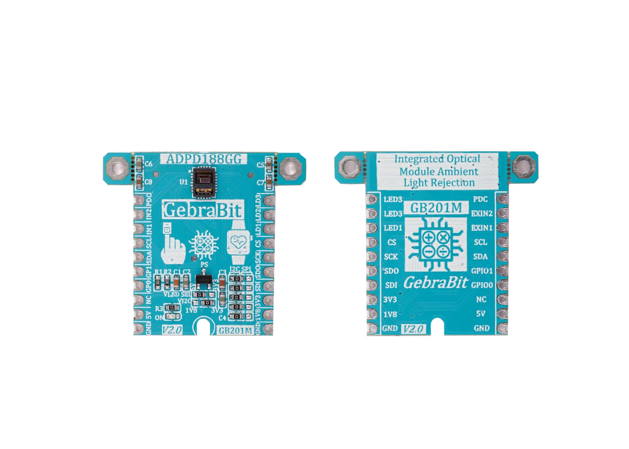
Gebra ADPD188GG modülü, entegre 1V8 regülatör sayesinde ADPD188GG sensörünü AÇIK konuma getirmek için 5V giriş Besleme Voltajına ihtiyaç duyar. Kullanıcılar Gebra ADPD188GG ile I2C veya SPI protokolü ile arayüz oluşturabilir. Bu, Gebra ADPD188GG modülünün sağ alt tarafındaki beş özel seçici jumper ile gerçekleştirilir.
Not: Gebra STM32F303 modülünün PA14 pininin mikrodenetleyiciyi programlamak için kullanıldığı düşünüldüğünde, PA14 ve PA15 pinlerinde I2C ayarı bu sürümde imkansızdır, bu nedenle Gebra STM32F303 modülü ile I2C bağlantısı için bu sürümde Gebra ADPD188GG modülü Pin to Pin olarak yerleştirilemez. Kolaylık sağlamak için, yerleşik jumperları kullanarak SPI protokolünü seçebilir ve ardından Gebra ADPD188GG modülünü Gebra STM32F303 modülüne Pin to Pin olarak yerleştirebilirsiniz.
Gebra ADPD188GG Özellikleri
- Kullanıcı tarafından seçilebilen I2C mantık seviyesi voltajı
- Kullanıcı Tarafından Seçilebilir ADPD188GG Yeşil LED Anot Besleme Gerilimi
- Kullanıcı tarafından seçilebilen arayüz protokolü (I2C veya SPI)
- 1V8 Voltaj Regülatörü
- 1V8 Çıkış Gerilimi
- Yerleşik, AÇIK/KAPALI LED göstergesi
- GEBRABUS ile Uyumlu Pin
- ADPD188GG’nin tüm önemli G/Ç’lerine erişim
- GEBRABIT MCU Modüllerinin ek kartı olarak kullanılabilir
- Kanatlı ped içeren (SMD Parçası olarak Birleştirilmiş)
- Tahtanın boyutunu azaltmak için ayrılabilir vida parçaları
- Paket: GebraBit küçük (36,29 mm x 32,72 mm)
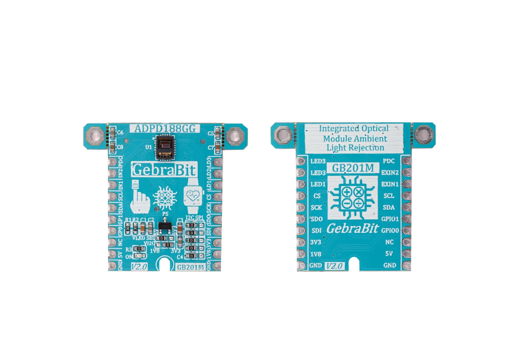
Pinout
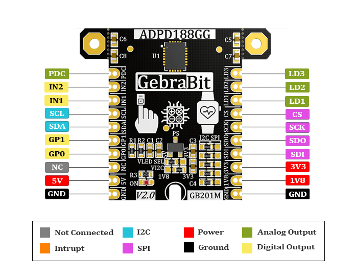
Modül bölümlerinin tanıtımı
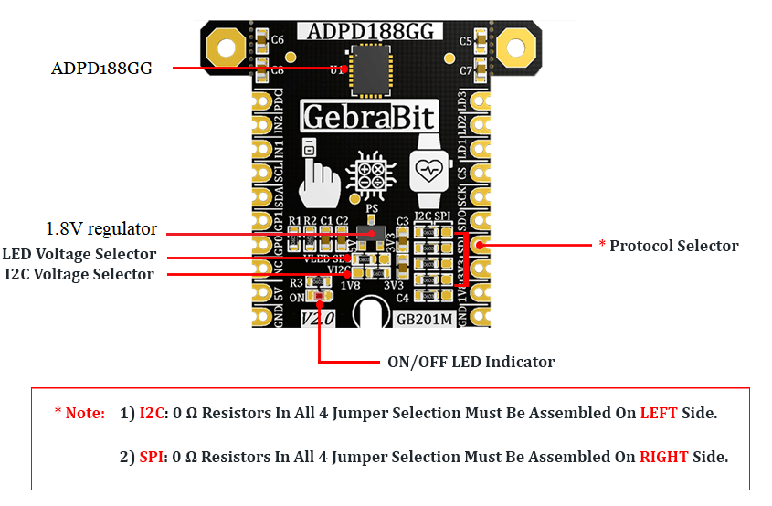
ADPD188GG sensörü
It’s the main IC of the following module, which its circuit is designed and is placed on top of the module and is in charge of optical heart rate monitoring and SPO2 measurement.
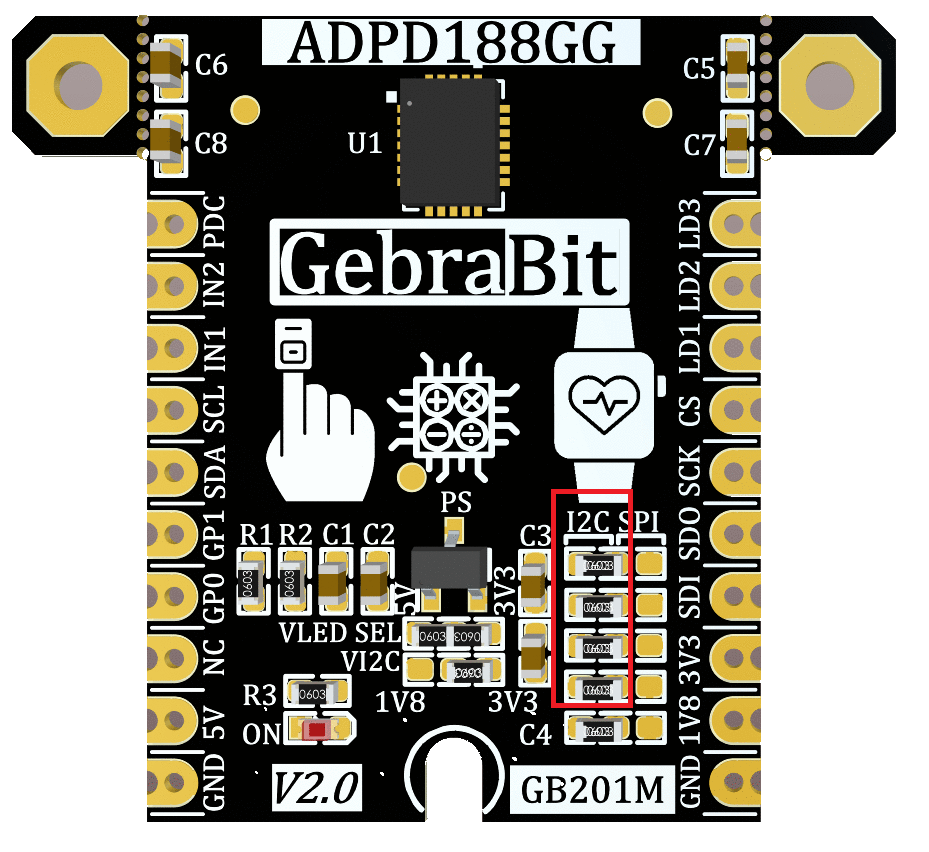
İletişim protokolü seçimi atlama telleri
If the 0R resistors of all Jumper Selectors are to the left side, the I2C protocol is selected. If the 0R resistors of all Jumper Selectors are to the left side, the I2C protocol is selected.
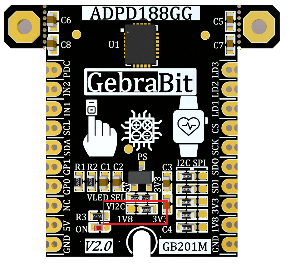
VI2C seçici atlama kablosu
According to the state of 0R resistance of this jumper the I2C logic level voltage of module can be selected between “1V8” or “3V3”.
LED voltaj seçici atlama kablosu (VLED SEL)
According to the state of 0R resistance of “VLED SEL” jumper, the ADPD188GG Green LED Anode Supply Voltage can be selected between “5V” or “3V3” .

“1.8V” XC6206P182MRG regülatör
In order to achieve 1V8 voltage of the I2C interface logic level, a 1.8V XC6206P182MR-G regulator is used on the GebraBit ADPD188GG module. Due to the existence of this regulator, 5V supply voltage is needed to activate the module sensor.

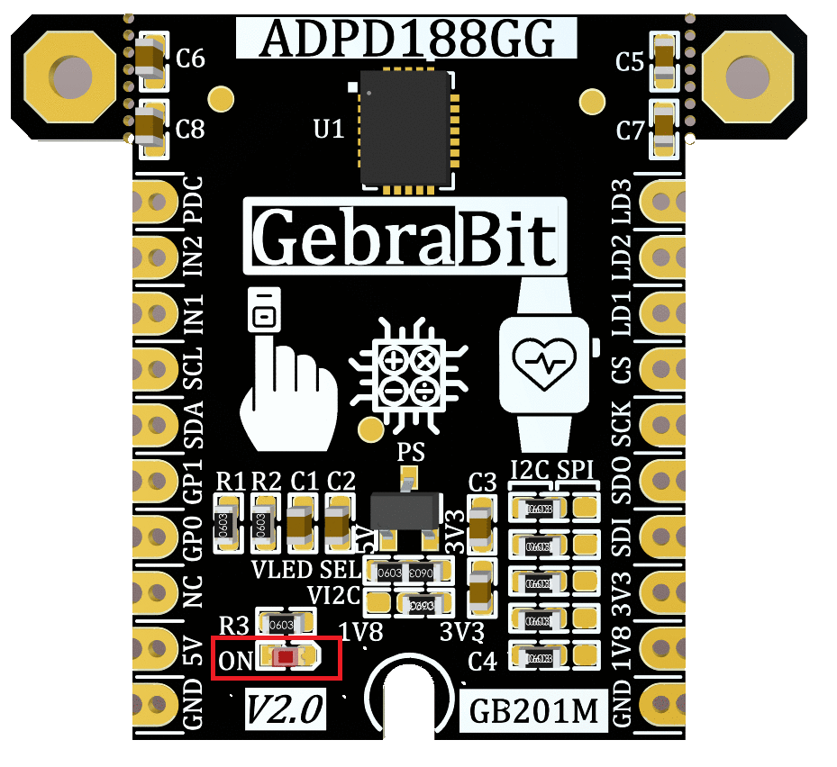
güç kaynağı LED’i
By applying voltage to the module via the corresponding pin, this LED will be lit.
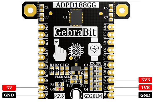
Supply pinleri
- 1V8 and 3V3 and 5V: These pins can provide the main power supply of the sensor and LED Anode Supply Voltage and the logic level of the sensor digital connection (I2C or SPI) according to the “VI2C SEL” and “VLED SEL” jumpers state.
- GND: This is the common ground pin for power the module.
I2C pinleri
- By using the on-board embedded Jumper selectors, you can choose the type of module communication . If the 0R resistors of all the Jumper Selectors are to the left side, the I2C protocol is selected.
- SDA: This pin is the I2C communication data pin, which is connected to the corresponding data pin in the microcontroller (processor). According to the state of the “VI2C SEL” jumper, you can use the logic level with a voltage of “1V8” or “3V3”.This pin is pulled up with a resistor.
- SCL: This pin is the I2C communication clock pin, which is connected to the corresponding clock pin in the microcontroller (processor). Depending on the state of the “VI2C SEL” jumper, you can use the logic level with a voltage of 1V8 or 3V3. This pin is pulled up with a resistor.

SPI pinleri
The type of communication with the module can be selected by using the on-board embedded Jumper Selectors. If the 0R resistors of all the Jumper Selectors are to the right side, the SPI protocol has been selected.
- SDI (MOSI): This pin is used to send data from the microcontroller (processor) to the module (sensor). The abbreviation of this pin is derived from the Latin phrase Serial Data In / Microcontroller Out Sensor In.
- SDO (MISO): This pin is used to send data from the module (sensor) to the microcontroller (processor). The abbreviation of this pin is derived from the Latin phrase Serial Data Out / Microcontroller In Sensor Out.
- SCK: This pin is the clock pin for SPI communication, which is considered as an input for the sensor and is connected to the corresponding clock pin in the microcontroller (processor).
- CS: This pin is the Chip Select pin for SPI communication with the module (sensor), which is selected by applying LOW voltage (0V), the module (sensor) for SPI communication. This pin is input type for the sensor.

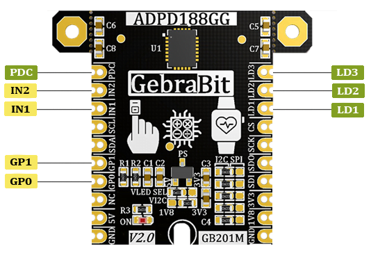
Diğer pinler
- GP0 and GP1: These pins are the GPIO0 and GPIO1 pins of the module, which can be used as general-purpose input/output pins.
- IN1 and IN2: These pins are the External analog current input pins.
- PDC: this pin is Photodiode Common Cathode Bias pin.
- LD1 and LD2 and LD3: These pins are the LED1, LED2 and LED3 Driver Current Sink pins.
Gebra STM32F303 ile I2C bağlantısı
First, make sure that the I2C protocol is selected by using the on-board jumpers, then for i2c communication of GebraBit ADPD188GG and GebraBit STM32F303 microcontroller module, after defining “SDA” and “SCL” on pins PB9 and PB8 (for convenience in STMCUBEMX), follow the below steps:
- Connect the “3V3” pin of the ADPD188GG module to the “3V3” output pin of the microcontroller module. (red wire)
- Connect the “GND” pin of the ADPD188GG module to the “GND” pin of the microcontroller module (black wire).
- Connect the “SCL” pin of the ADPD188GG module to the PB8 pin of the microcontroller (SCL) module (blue wire).
- Connect the “SDA” pin of the ADPD188GG module to the PB9 pin of the microcontroller (SDA) module. (yellow wire)

Gebra STM32F303 ile SPI bağlantısı
First, make sure that the SPI protocol is selected by using the on-board jumpers, then for connecting GebraBit ADPD188GG module to the GebraBit STM32F303 microcontroller module with SPI protocol, after defining “SDI”, “SDO”, “SCK”, and “CS” on pins PB5, PB4, PB3, and PC13 ( For ease of work in STMCUBEMX) place the GebraBit ADPD188GG module Pin to Pin on the GebraBit STM32F303 module easily. Here for better understanding the separate connection of these two modules is also shown.


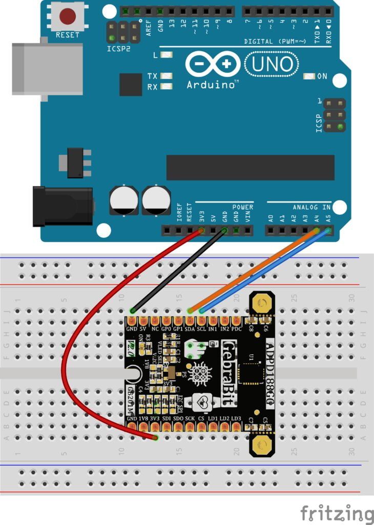
ARDUINO UNO ile I2C Bağlantısı
First, make sure that the I2C protocol is selected by using the on-board jumpers, then follow the below steps to connect the GebraBit ADPD188GG module to the ARDUINO UNO via I2C :
- Connect the “3V3” pin of the ADPD188GG module to the “3V3” output pin of the ARDUINO UNO board. (red wire)
- Connect the “GND” pin of the ADPD188GG module to the “GND” pin of the ARDUINO UNO board (black wire).
- Connect the “SCL” pin of the ADPD188GG module to the A5 pin of the ARDUINO UNO board (SCL). (blue wire)
- Connect the “SDA” pin of the ADPD188GG module to the A4 pin of the ARDUINO UNO board (SDA). (orange wire)
ARDUINO UNO ile SPI Bağlantısı
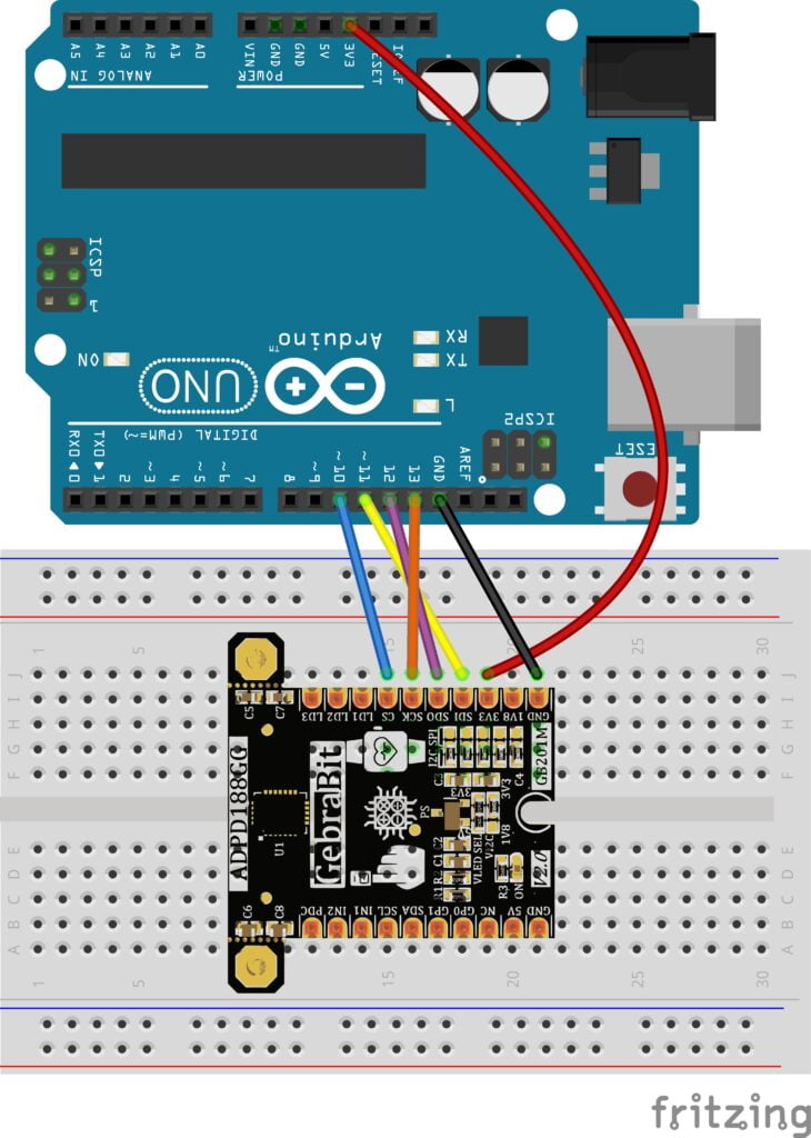
First, make sure the SPI protocol is selected using the on-board jumpers, then follow the below steps to connect the GebraBit ADPD188GG module to the ARDUINO UNO via SPI:
- Connect the “3V3” pin of the ADPD188GG module to the “3V3” output pin of the ARDUINO UNO board. (red wire)
- Connect the “GND” pin of the ADPD188GG module to the “GND” pin of the ARDUINO UNO board (black wire).
- Connect the “SDI” pin of the ADPD188GG module to the D11 pin of the ARDUINO UNO board (SDI). (yellow wire)
- Connect the “SDO” pin of the ADPD188GG module to the D12 pin of the ARDUINO UNO board (SDO). (Purple wire)
- Connect the “SCK” pin of the ADPD188GG module to the D13 pin of the ARDUINO UNO board (SCK). (Orange wire)
- Connect the “CS” pin of the ADPD188GG module to the D10 pin of the ARDUINO UNO board (SS). (blue wire)
